Question
How do I use a JFET to regulate LED current?
Answer
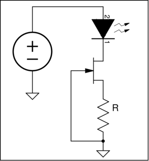
With negative feedback a junction FET (JFET) can be used as a
adjustable current regulator. The circuit on the right uses the
resistor (R) to set the current through the LED. As long as the
drain-to-source voltage (V
DS) is above a minimum value a
constant current flows through the LED.
Calculation Example
The value of R is calculated using the "Drain Characteristics" curve
available in the JFET datasheet. The graph shown is from the On-Semi
BFR30LT1 datasheet.
Since the y-axis is drain current (ID) horizontal
lines are constant current. For each gate-to-source voltage
(VGS) there is a minimum drain-to-source voltage
VDS above which ID is constant.
For example to maintain a current of 2.5mA a VGS of -3V is
required. The resistance R would be --
The minimum voltage for regulation is
Using an LED with a forward voltage (V
F) of 2V and the
BFR30LT1 at a V
GS of -3V the minimum voltage for regulation
is ≈ 5V. For voltages above 5V constant current is maintained.
A couple of other useful values can be read from the
curves. VGS(OFF) is the value of gate-to-source voltage
that forces the JFET drain current to zero (-5.8V for the
BFR30LT1). The zero-gate-voltage drain current (IDSS) is
the current that flows when VGS is zero (≈ 9mA for
the BFR30LT1). IDSS is the maximum current of the JFET.