ZB1 Thru-hole Kit Assembly (Rev3 Boards)
Semiconductors are electrostatic-sensitive devices. Proper ESD
handling precautions need to be taken to avoid damage.
Sort Components
Sort the components into the groups shown in the instructions
below.
All of the headers supplied with the kit are breakaway
headers. The single row headers, J3 (3x1), J5 (6x1), J9 (3x1), J11
(3x1) may come as individual headers or as strips that need to be
broken. The double row vertical headers J6 (3x2), J4 (6x2) and J7
(2x2) may come as individual header or as strips that need to be
broken.
Assembly Steps
- Solder the SMD and thru-hole bottom side components
- Solder the power supply circuit components and then test
the power supply circuit.
- Solder the microcontroller circuit components.
- Solder the electro-mechanical components and
then test the microcontroller circuitry.
- Solder the XBee components.
Bottom Side Components
SMD Components
One SMD component, F1, is included in the ZB1-KIT2 kit. An
easy way to install F1:
- Flux both pads of the component footprint.
- Reflow solder on one pad of each component footprint.
- While holding the SMD component with tweezers slide
one of the metalized end into the molten solder.
- Solder the other end of the component footprint.
Optional components U3 and C7 are used to provide a 3.3V supply for the XBee
using the +5V from J4. See the datasheet for more information
Thru-hole Components
- Solder C2, C3
- Solder R3, R5
The tolerance of R3 and R5 is not critical. Some kits include 5% resistors
others include 1% resistors. Both types of resistors are pictured to the right.
The 5% resistor has four color bands (red, red, brown, gold). The 1% resistor
has five color bands (red, red, brown, black, brown).
Top Side Components
Power Supply Circuit
- C10, C11
C10 and C11 are polarized parts. The long lead is the positive.
The short lead is the negative. Make sure that the positive
lead is inserted into positive hole in the PCB
- U4
Be careful to not mixup U4 and D3. U4 is marked
MC33269T-3.3G
Make sure that the tab is aligned to the tab marking on the PCB.
- D3
Be careful to not mixup D3 and U4. D3 is marked
MBR1545CTG Make sure that the tab is aligned to the tab
marking on the PCB.
- J9
- J10
- J8 (optional, not in all kits)
J8 enables the usage of an external 3.3V power source with the ZB1. If you
do not need this function then you can omit the installation of J9.
Testing the Power Supply Circuit
Power the board with a 5V supply through J10. The current drawn from
the +5V supply should not exceed a few milliamperes. An easy place to
measure the output voltage of U4 is pin one of J9. The voltage should
read 3.3V. If there is excessive current or the voltage is accuracy is
not within ± 2% quickly shut off the 5V supply and verify the
orientation on C10, C11, D3, U4.
Microcontroller Circuit
- R1
The tolerance of R1 is not critical. Some kits include a 5% resistor
others include a 1% resistor. Both types of resistors are pictured to the right.
The 5% resistor has four color bands (brown, black, orange, gold). The 1% resistor
has five color bands (brown, black, black, red, brown).
- D6, C13, C1
Line the cathode marking on D6 with the cathode marking on the silkscreen.
- L1
The value of inductor L1 is not critical. Kits will contain an
inductor with a value between 10uH and 15uH. Pictures of a 10uH
and a 12uH are shown on the right.
- D4
The negative lead of the LED is the short lead. Align the short lead with
the negative marking on the PCB.
- R2
The tolerance of R2 is not critical. Some kits include a 5% resistor
others include a 1% resistor. Both types of resistors are pictured to the right.
The 5% resistor has four color bands (red, red, brown, gold). The 1% resistor
has five color bands (red, red, brown, black, brown).
- J3
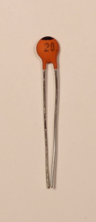
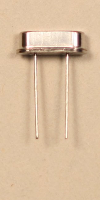
- X1, C5, C9
- U1 (socket)
- J6
- J5
- J1
The J1 that is included with the ZB1 Kit is a right angle
connector. If your application requires parallel board mounting or a
cable connection then replace J3 with a vertical header. A 2x13 receptacle
can also be used.
XBee Components
- C4, C12
- J4
- J7
- J11
- D1, D2
The negative lead of the LED is the short lead. Align the short lead with
the negative marking on the PCB.
- XBee Headers (2)
Optional connector J2 is used to connect to DIO-DIO5 of the XBee.
Electromechanical Components

| S2
|
|

| S3, S1
|
|
|
- S2
- S1, S3
- Install the appropriate jumpers (see the datasheet).
Test
Remove the ATmega168 from the antistatic foam and insert it into the
U1 socket aligning the notch in the IC package with notch mark
indicated on the PCB silkscreen. Be careful to align pins on both
sides of the socket prior to pressing the IC into the socket.
The board is now ready to program. See the
datasheet
for application hints.